How to install a DS-2 Player
DS-2
Connecting your DS-2
Prior to configuration, please ensure the product is properly seated on a flat, secure surface and housed in a suitable area with ample provision for convection airflow and heat dissipation. Avoid direct contact with sources of heat such as heating systems or audio amplifiers. The operating environment must stay within the specified operating temperature and humidity.
A suitable wired or wireless network is required. Access to the Internet may be required to use some features of the product.
-
If using a wired network, connect the network Ethernet cable to the DS-2
-
If using a WiFi network, connect the antenna to the DS-2
Connections to 3rd-party equipment
Please check the DS-2 I/O configuration BEFORE connecting 3rd-party equipment. See DS-2 Hardware Configuration for more information.
All connectivity to 3rd-party equipment must be completed whilst the DS-2 is disconnected from power (DC power pack or PoE) and is off.
DS-2 extended connectivity ports:

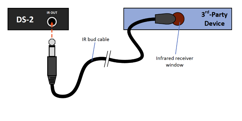
For IR connections, connect the IR emitter bud cable to the DS-2 and mount the emitter end next to the IR receiver windows on your 3rd-party equipment.

For RS-232 serial connections, connect the terminals with a cable between the DS-2 RS-232 port and the RS-232 port on the 3rd-party equipment.
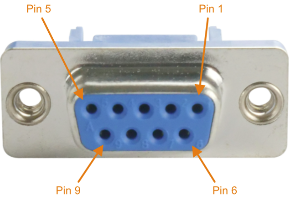
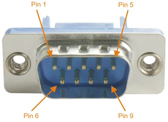
On the equipment to be connected, refer to the table below depending on what connector the 3rd-party equipment is using:


| DS-2 Pin | Connect to | Terminals | DE-9F Pin (DCE) | DE-9M Pin (DTE) |
| GND | -> | GND Ground | 5 (Signal Ground) | 5 (Signal Ground) |
| TX | -> | RX RXD | 3 (TxD) | 2 (RxD) |
| RX | -> | TX TXD | 2 (RxD) | 3 (TxD) |
For digital GPIO connections, connect the terminals with a cable between the DS-2 I/O port and the port on the 3rd-party equipment. Some connection examples are shown below:
Depending on your application, you may need to refer to the documentation that accompanies your 3rd-party equipment.
By default the DS-2 I/O pins are set as INPUTS. By default the V+ pin is set to 5V.